HELP DESK
Help with installation:

The Maxhaust Bridge is the All-In-One interface for all Maxhaust products and the Bridge app.
All Maxhaust extensions such as Active Sound and all future extensions such as air suspension, flap control, pedal tuning or ambient lighting are controlled and managed with the bridge.
CABLE SET
The cable set for the MAXHAUST BRIDGE is required for the power supply and for the connection to the vehicle CAN bus.
For all work on the vehicle electrics, the vehicle ignition must be switched off!

POWER SUPPLY
+ POWER CONNECTION
The red cable from the cable set must be connected to permanent plus (terminal 30) on the vehicle side.
To make this easier, the cable set comes with four different current taps.
After selecting the right electricity thief, it is crimped with the blue crimp connector.
Alternatively, the two cable ends can also be soldered together.
1. Strip the end of the red cable

2. Plug the cable into the crimp connector of the power connector

3. Squeeze the crimp connector with pliers

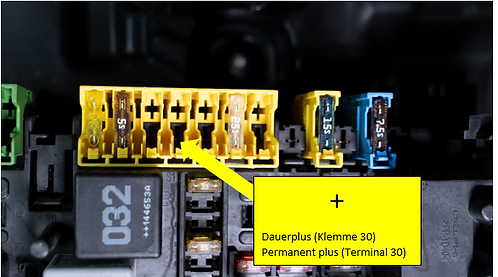
POWER CONNECTION AT THE FUSE CARRIER
The current should only be taken from the vehicle´s fuse carrier.
To do this, use a current tester to find a free or occupied fuse location with a steady plus (terminal 30).
EXAMPLE1:
Current collection at a free slot.

In this example, the upper contact strip is the current-carrying one. This is supplied with voltage when the ignition is switched off and can be used as a slot for the current tap.

The appropriate current tap can now be plugged in depending on the type of fuse.

EXAMPLE 2:
Current collection at an occupied slot.
Here in the example we remove the 10A fuse (red) and measure whether and on which contact there is a permanent plus.

The removed 10A fuse (red) is now inserted in position B on the current tap.
The 15A fuse (blue) position A must remain in the specified position.


Now the current tap is put back into the fuse slot.
It is important that the current tap is plugged in in the correct position.
The one marked in figure the + contact of the current feeder must also be in the fuse carrier + contact can be plugged in.


- GROUND CONNECTION
The black cable (ground terminal 31) must be connected to the vehicle body. It is important to ensure that there is good contact between the body and the cable lug. It is preferable to use existing ground points on the vehicle.
For example, to pick up the mass directly on the body or at a mass point of the vehicle.

CAN BUS
CAN BUS CONNECTION
The black/yellow cable (CAN low) and black/white cable (CAN high) must be connected to the vehicle´s CAN BUS system using the supplied CAN BUS connectors.
The CAN BUS cables on the vehicle are vehicle-specific and have different colors. However, in all vehicles, the CAN BUS cables (high and low) are usually twisted together.
1. The CAN BUS cables on the vehicle are vehicle-specific and have different colors. However, in all vehicles, the CAN BUS cables (high and low) are usually twisted together.

2. Untwist the CAN BUS cable on the vehicle.

3. Insert the CAN BUS connector into the CAN BUS connector as shown.
Example:
• CAN high cable set (black/white) on CAN high vehicle (orange/black)
• CAN low cable set (black/yellow) on CAN low vehicle (orange/brown)

4. Close the CAN BUS connector and carefully press with pliers until the connector snaps into place.

You can find out where you can find the CanBus in your vehicle and how it is connected in the vehicle-specific instructions. You can find out how to get these here.
CONNECTION BRIDGE
Now just connect the cable to Port A of the MAXHAUST BRIDGE.

